It’s not you, it’s me
Actually, I lied. It’s you.
bgfx is no longer relevant to the project. Why? Well, I wasn’t doing all that much with it and really it’s not benefitting me that much. Easy window creation? It uses SDL for that. Easy rendering? Well, you still have to use OpenGL and for vector stuff you can use NanoVG. So why not use NanoVG directly?
And SDL won’t help hide away the X11 vs native Pi window creation anyway.
So that’s what I did. A little Screen class to hide the OpenGL ES stuff. Now, as I’m doing my main development on my Linux desktop, I need to create the native X11 window. For the Pi, you can use some Broadcom headers (that also allow you to use GPIO) to create this window without X11, so that’s something I can integrate at a later date.
It has to be said that I wasted quite a bit of time trying to figure out why my OpenGL ES window creation didn’t want to paint. It resulted in a blank X11 window with some garbage in it. This turned out to be because there was a slight problem with my build setup. Not all of the OpenGL ES libraries were being linked, whereas there were proper OpenGL libraries. This caused an incompatibility that means all calls were succeeding but not actually doing anything. Ugh.
This all brings me to another problem. Third party libraries in general. It takes time to learn them and so often they don’t do exactly what you need, so you spend time working around the library to make it do that.
This applies more to the niche libraries that I’ve been trying to use than the more mature ones I’ve used in the past though.

Failure
Something that’s been bugging me lately is robustness.
Catastrophic
There are a few components that can fail catastrophically.
Arduino
As this acquires all sensor data, so if it fails, we’re flying blind. In order to remedy this, some manner of redundant Arduino could be used. The Pi has at least 2 native serial ports, so that would be achievable.
Pi
If the Pi fails, we’re pretty dead. It drives the screen. One solution would be to have two running and try to combine the signals from both Pis to the board. HDMI isn’t the best protocol for it, being encrypted and stuff like that.
Display board
This is a cheap board, it’s likely to fail in some way. Failure would be very bad, it would kill any output. I’d wager this fails before the Pi or Arduino. Is dual board an option? It could be. The output is a simple ribbon.
Screen
The screen could fail too. In my lifetime of many monitors I’ve not seen one fail after successful running for a while. There’s nothing much that can be done about the failure. Having dual screens wouldn’t do much.
Connections
Connections can come loose. After speaking to a friend who’s also doing things with Arduinos, perhaps I should use automotive grade locking headers.
A likely source of trouble would be the vibrations. Designing the frame so that the electronics live suspended from some rubber mounts would possible extend the lifetime.
Subtle failure
This is a tricky category. What’s even worse than total failure? Getting a wrong result and not knowing about it.
Arduino
The most likely problems here would be incorrect calibration, some kind of wiring harness problems. As we’re doing ADC, it’s possible that we get some outside interference. Not unhead of to have some random errors. This can be generally filtered out in the Pi.
If there is a more serious failure, like a non response, the Arduino can be soft reset by the Pi through GPIO. Perhaps cutting the Vin through GPIO would be an option too.
Pi
The Pi would be best served by general defensive programming and thorough error checking. As we were merely monitoring, a hard fail is an option. Providing we can restart quickly, running the executable in a loop could be acceptable. There isn’t a great deal of variance, so once we’re up an running there really shouldn’t be any reason for failure.
Display board
A reset would be possible here. There is a simple control board with buttons. Problem being is that we wouldn’t know when to do it.
Screen
If this fails, we can’t detect it, so that’ll be up to the driver.
Connections
Had better solder well..
Star Trek
Whenever something fails in any of the Star Trek series fails, there always seems to be an explosion. Yet I don’t think that other than fuel related problems, any space craft so far has had any problems with exploding consoles. Why would you even put something that could explode so close to the interface? Wouldn’t you keep that in a Faraday cage some distance then operate it with servos?
This especially bugs with be Star Trek: Enterprise. The NX01 is your first prototype. Before you send something so precious out, wouldn’t you sort something like that out. In fact, once you have discovered it, why wouldn’t you solve in within several hundred years?
I SPI with my little I
This whole SPI thing is a bit complicated for what is essentially a quite simple thing. As it has a master/slave system, the naming can be slightly confusing as the labels are flipped for the slave devices.It’s effectively just 4 wires:
- Serial Clock (aka SCK, SCL, SCLK), same for master & slave
- Master Output, Slave Input (aka MOSI, SDI for master, SDO for slave)
- Master Input, Slave Output (aka MISO, SDO for master, SDI for slave)
- Slave select (aka SS, CS), same for master & slave
As multiple devices can be on the same bus, the slave select is used to determine which of the devices should be active. In programmer terms, a kind of semaphore signalling to all the devices which one is supposed to talk.
A minor complication is that there can be a 3 wire version, in which the SDI and SDO are combined into SDIO. The datasheet for the accelerometer I’m usingPDF alert has a nice diagram with the difference:

The accelerometer board supports both I2C and SPI but the pins printed use the I2C labels. This is great if you want to hook it up via SPI but slightly confusing if you don’t.
The manual has the following pin out for the actual chip:
| Pin No. | Mnemonic | Description |
|---|---|---|
| 1 | VDD I/O | Digital Interface Supply Voltage. |
| 2 | GND | Must be connected to ground. |
| 3 | Reserved | Reserved. This pin must be connected to VS or left open. |
| 4 | GND | Must be connected to ground. |
| 5 | GND | Must be connected to ground. |
| 6 | VS | Supply Voltage. |
| 7 | CS | Chip Select. |
| 8 | INT1 | Interrupt 1 Output. |
| 9 | INT2 | Interrupt 2 Output. |
| 10 | NC | Not Internally Connected. |
| 11 | Reserved | Reserved. This pin must be connected to ground or left open. |
| 12 | SDO/ALT ADDRESS | Serial Data Output/Alternate I2C Address Select. |
| 13 | SDA/SDI/SDIO | Serial Data (I2C)/Serial Data Input (SPI 4-Wire)/Serial Data Input and Output (SPI 3-Wire). |
| 14 | SCL/SCLK | Serial Communications Clock |
A-ha!
It stands to reason that they just used the first label. As I want to hook it up, I need to hook up CS to the slave select, SDA to the SDIO port and SCL to the clock. I’ll be able to leave the SDO pin empty or connect to the ground.
So hardware problem solved, now it’s a software problem. Yeay?
The central idea would be to stick to the ICPS header, so that I get the maximum of pins available for my other acquisition. In order to the the 3 wires, I’ll have to use one of the MOSI/MOSI pins as the CS, with the other one being SDIO. SCK can remain SCL.
The sensor library provides by adafruit does support both I2C and SPI but the SPI constructor demands the traditional 4 wires. It doesn’t use the SPI library but instead the raw writing to pins. I think that’s actually a good thing, as the SPI library doesn’t seem to list any options for 3/4 wire. To do the appropriate things, I’ll have to alter the library to cope with the MOSI and MISO pins being one and the same. Or do I?
The central method in the library is spixfer(). That simply writes to the mosi pin and reads from the miso.
static uint8_t spixfer(uint8_t clock, uint8_t miso, uint8_t mosi, uint8_t data) {
  uint8_t reply = 0;
  for (int i=7; i>=0; i--) {
    reply <<= 1;
    digitalWrite(clock, LOW);
    digitalWrite(mosi, data & (1<<i));
    digitalWrite(clock, HIGH);
    if (digitalRead(miso))
      reply |= 1;
  }
  return reply;
}
Well, that could work, couldn’t it?
Just to confirm, according to the Instructables:
The extra pins have been mapped to the ICSP header. Their mappings are:

    D14 – MISO – PB3
    D15 – SCK – PB1
    D16 – MOSI – PB2
    D17 – SS – PB0
(At this point you may wonder “but I thought you said there wasn’t a Slave select in the header?” Well, there isn’t. The pin is present on the board but it’s hooked up to pin 17, which is the RX LED. If I wanted to use it, I’d have to do some resoldering to get access to the pin.)
That means we get the following mapping (in tabular form):
| Left row | Right row | ||
|---|---|---|---|
| 14 | MOSI | Vcc | – |
| 15 | SCK | MOSI | 16 |
| – | Reset | GND | – |
- MISO = CS
- MOSI = SDIO
- SCK = SCK
This means I should be able to use the constructor like so:
Adafruit_ADXL345_Unified(16, 15, 15, 14);
Well, no magic smoke has been released, but the device isn’t being reported as connected. Because the subtle differences between the 3 and 4 wire version, I’ll have to make some small alterations to the sensor code.
Rendering/OpenVG
TWO posts in one day?!
OpenVG
OpenVG has been a bit of a question mark even when I started this project. While very interesting and the sort of thing I was after, it hasn’t really taken off. There’s a handful of library that support it but the most popular (ShivaVG) doesn’t even implement fonts. That shows it’s not really where it should be, realistically.
Additionally, I had quite a lot of trouble reading SVG files into OpenVG and getting it to render properly. This is probably my own fault but doesn’t bode very well regardless.
Even so, none of the OpenVG libraries seem to have been touched in quite a few years, some cases 5-7 years. What does Netcraft say?
NanoVG has been something that’s been rearing its head much more and have encountered it in past projects. Another thing that has popped up is that I can’t really do much development on the Pi, so I have to either test it on my computer or cross build and deploy on the Pi and try it there. Obviously it’s much easier to do the testing on the computer, it’s much more powerful and quicker to try things.
Rendering
Another thing I encountered is bgfx, which claims to be a Cross-platform, graphics API agnostic, “Bring Your Own Engine/Framework” style rendering library. That does sound quite appealing, as I’m lazy in terms of OpenGL. The shader pipeline requires a lot of code which anyone would rather avoid writing if they can.
Interestingly enough they list how many draw calls they can made to keep 60Hz on a Pi 216. This doesn’t sound particularly impressive, but it might just do the trick. Furthermore, they support NanoVG.
So, we get:
- NanoVG for vector drawing
- Integrated fonts, etc
- Cross platform
- Shader support
- Allowing my own engine
- Less OpenGL ES code to write
- And last, but not least: it’s under active development!
Using this would mean I spend less time dealing with drawing, more time with getting the data acquisition and processing right.

Latest sensor update
Pressure: 1017.50 hPa; Temp: 25.70 C
It appears to be getting hot in here.
More data
So I figured that I needed a level shifter for the serial connection as the Leonardo is 5V device and the Pi is 3.3V. While I was shopping at Pimoroni, I had a little look at the sensors section. Oh boy.
I ended up getting an ADXL345 3 axis accelerometer and a BMP180 Pressure sensor.
My first thought at hooking them up was through the Pi, as that supports I2C on two ports but as I tried getting that working, it occurred to me that the Arduino was a much better place. Keeping the data acquisition in one place and the visualisation in another. Sort of in keeping with the MVC model, with the Leonardo being the M and the Pi being the VC.
Temperature
After some messing about, the BMP was actually quite simple to integrate:
- Hook up Arduino’s 3.3V to the Vin
- Hook up Arduino’s ground to ground
- Hook up SCL and SDA to the Leonardo’s dedicated SCL and SDA pins.
- Add the Adafruit sensor package to the source
That latter step looks something like this:
- git clone the Adafruit_Sensor repo into the Arduino’s sketchbook/libraries folder
- git clone the Adafruit_BMP085 repo into the Arduino’s sketchbook/libraries folder (the BMP085 is a previous revision of the BMP180 which is entirely compatible
- Add the below code, given example from Adafruit
#include <Adafruit_Sensor.h>
#include <Adafruit_BMP085_U.h>

...

Adafruit_BMP085_Unified bmp = Adafruit_BMP085_Unified(10085);

void setup() {
  ...

  /* Initialise the sensor */
  if(!bmp.begin())
  {
    /* There was a problem detecting the BMP085 ... check your connections */
    Serial.print("Ooops, no BMP085 detected ... Check your wiring or I2C ADDR!");
    while(1);
  }

  ...
}

void loop() {
  ...

  sensors_event_t event;
  bmp.getEvent(&event);
  /* Display the results (barometric pressure is measure in hPa) */
  if (event.pressure)
  {
     float temperature;
     bmp.getTemperature(&temperature);
    /* Display atmospheric pressure in hPa */
    Serial.print("Pressure: "); Serial.print(event.pressure); Serial.print(" hPa;");
    Serial.print(" Temp: "); Serial.print(temperature); Serial.println(" C");
  }

  ...
}
This very happily prints the current pressure and temperature in my room:
Pressure: 1017.11 hPa; Temp: 25.30 C
The barometric pressure isn’t all that interesting to me, it’s the temperature I care about more. Really I could do with two sensors, inside and outside temperature but this’ll do for now. One of my concerns with this would be from the source that it’s doing a lot of stuff that I’m not necessarily interested in. I’ll take in the wise words from Mr Knuth in that premature optimization is the root of all evil, so when I’ve finished with all the data acquisition I’ll do some profiling to see if it’s actually an issue.
Accelerometer
As for the accelerometer, well, that’s supposed to be an I2C and SPI device. The Leonardo’s dedicated I2C pins are being taken by the temperature sensor, so that leaves the SPI. Luckily the Leonardo also has some dedicated SPI in the form of the ICSP header.
According to the reference the Leonardno has ICSP-4 as MOSI (isn’t that how Japanese answer the phone?), ICSP-1 as MISO (Oriental prince in the land of SOUP!) and ICSP-3 as SCK with no SS.
Very helpfully (he said sarcastically) the ADXL is labelled with Vin, 3.3V, CS, INT1, INT2, SDO, SDA and SCL. Which are I2C labels. There is a tutorial at sparkfun how to hook up the ADXL to an Arduino with SPI, but it still uses the I2C pins. For most Arduino boards these pins double up for SPI but the Leonardo is slightly different in that the SPI is only present on the ICSP header. That means I don’t really know which pins go where.
Lucky the people at Adafruit also have a sensor library for the ADXL which supports both I2C and SPI modes, depending on which constructor is used. Reading the code, to enable SPI you have to specify which pins to use, which should be straightforward with the Leonardo. However still leaves the matter as to where the MOSI, MISO and SCK pins go. There’s one chap(ette) on the Sparkfun tutorial mentioned above that the following should apply:
| 10 | -> | CS |
| MO(MISO) | -> | SDA |
| MI(MOSI) | -> | SDO |
| SCK | -> | SCL |
Which is ok for the 4 pin SPI connection, but the header on the Leonardo is like this:
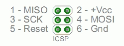
To my reckoning that means I only have 3 pins available. The CS is the question here. I don’t want to sacrifice one of the other pins for that if I can.
I’ll have to do a bit more reading before I proceed with this.
Latest reading on pressure & temperature
Pressure: 1017.27 hPa; Temp: 25.60 C
Sketch
The Arduino code in base is pretty simple..
const int ledPin = 13;
const int sizeOfDataPacket = 8;
unsigned int counter = 0;
unsigned int dataPacket[sizeOfDataPacket];

void setup() {
  pinMode(ledPin, OUTPUT);

  Serial1.begin(9600);

  /* Signal we're alive */
  tone(ledPin, 5, 1000);
}

void loop() {
  /* Reset data */
  dataPacket[0] = dataPacket[1] = dataPacket[2] = dataPacket[3] =
    dataPacket[4] = dataPacket[5] = dataPacket[6] = dataPacket[7] =  0;

  /* Assemble data */
  dataPacket[0] = 7; // Version
  dataPacket[1] = counter++; // Counter

  /* Read analog inputs */
  dataPacket[2] = analogRead(A0);
  dataPacket[3] = analogRead(A1);
  dataPacket[4] = analogRead(A2);
  dataPacket[5] = analogRead(A3);
  dataPacket[6] = analogRead(A4);

  /* Read digital input. Int is 16 bits so max 16 values. */
  bitWrite(dataPacket[7], 0, digitalRead(2) == HIGH);
  bitWrite(dataPacket[7], 1, digitalRead(3) == HIGH);
  bitWrite(dataPacket[7], 2, digitalRead(4) == HIGH);
  bitWrite(dataPacket[7], 3, digitalRead(5) == HIGH);
  bitWrite(dataPacket[7], 4, digitalRead(6) == HIGH);
  bitWrite(dataPacket[7], 5, digitalRead(7) == HIGH);
  bitWrite(dataPacket[7], 6, digitalRead(8) == HIGH);
  bitWrite(dataPacket[7], 7, digitalRead(9) == HIGH);
  bitWrite(dataPacket[7], 8, digitalRead(10) == HIGH);
  bitWrite(dataPacket[7], 9, digitalRead(11) == HIGH);
  bitWrite(dataPacket[7], 10, digitalRead(12) == HIGH);

  /* Write data. Unfortunately write only does ints or char *,
     the int buffer has to be written one int at a time.. */
  digitalWrite(ledPin, HIGH);
  for (int i = 0; i < sizeOfDataPacket; i++) {
    Serial1.write(dataPacket[i]);
  }
  digitalWrite(ledPin, LOW);

  delay(1000);
}
Seems to work ok, though the Serial monitor is a bit useless, it only really deals with ASCI data, not binary stuff.
Something that did occur to me is that there definitely are more flags, however I don’t have enough pins on the Leonardo. I’ll have to use some of the GPIO pins on the Pi for that. To make things consistent, I’d have to switch to an Arduino Due or Mega. I might do that for consistency reasons, and to use the Leonardo for something else. (Who knows what!)
Data

The main point of this whole exercise is data. Acquiring it from the analog sources, converting it to something digital in the Arduino, acquiring the digital data in the Pi and displaying that in a timely fashion.
Arduino
If this were a C/C++ application, I would define some kind of data structure that would be shared on the Arduino and the Pi. One would fill one, transmit it, the other decode it and read it. Unfortunately the Arduino language is C based, it doesn’t offer structs. Best we can do is arrays.
Values
Lets first enumerate the values we have to transmit:
- Speed
- RPM
- Fuel level
- Boost pressure
- Engine temperature
- Indicator right
- Indicator left
- Check engine
- Parking brake
- Check oil level
- Check oil pressure
- Check fuel level
- Check ABS
- Check air bag
- Fog light
- Hazards
So that’s 16 values and most of them are only Boolean values. Yet a few of them offer a range.
Let’s expand that list into something more useful.
| Value | Type | Range |
|---|---|---|
| Speed | float | 0-300km/h |
| RPM | Int | 0-10000 |
| Fuel level | Range | Empty-full |
| Boost pressure | Range | –+ |
| Engine temperature | Range | Cold-Hot |
| Indicator right | bool | 0-1 |
| Indicator left | bool | 0-1 |
| Check engine | bool | 0-1 |
| Parking brake | bool | 0-1 |
| Check oil level | bool | 0-1 |
| Check oil pressure | bool | 0-1 |
| Check fuel level | bool | 0-1 |
| Check ABS | bool | 0-1 |
| Check air bag | bool | 0-1 |
| Fog light | bool | 0-1 |
| Hazards | bool | 0-1 |
Size consideration
If we express every value as a singular item in the array, we have to make everything as big as the biggest value in terms of resolution, which would be either speed or RPM. We need at least integers to capture those values.
An int is 2 bytes on a Arduino with each byte being 16 bits, so 11×2 bytes would be 22 bytes, or 352 bits. That’s a bit inefficient.
Luckily the Arduino language has bit operators, so we can compress the 11 bool values into one int.
It is worth bearing in mind that the analog resolution of the arduino is 1024 levels, so while a char would be too small, an int is way too big.
Other considerations
The above is all good and well but I can of course change my mind, so we need something to identify, a header. Maybe something timing is a good idea? The timestamps provides by milli() and micro() are unsigned longs. Making the entire array to be longs just to fit a timestamp for debugging would be crazy. Let’s just reserve one int, so we can create diff timestamps or serial numbers or something?
Make it so
So we can have an array of ints:
- Header
- Timestamp
- Speed
- RPM
- Engine temp
- Boost pressure
- Fuel level
- Flags
This gives us 8x 2 bytes, or 16 bytes and 256 bits. Based on 9600bps, which is the standard rate of the serial port, that would give us 37 updates a second. Which would be a bit disappointing. The port on the Leonardo and Pi should both be able to do 112500bps, which would be 439 updates a second, which would give an update every 2.3ms.
It’s worth bearing in mind, that no matter how quick the transmission is, the screen should refresh at 60fps, which is every 16ms. At 112500bps, the most we can transmit in a 16ms window is 1800 bits, that gives us enough space, no matter what.
Acquisition
There are 6 analog inputs and 11 digital ones (13 pins, minus 2 for the serial port). So given the table above, that lives us with no extra pins for any other flags and 1 space analog data acquisition port. Eek!

Or as Ace would say..

The only problem now is that I don’t have any inputs to test.
Undead

It’s been a while since I’ve updated this. Unfortunately work has taken up most of my time. Boo.
In the time that the project has been idling, the prototype has been sitting on my desk and while it’s been gathering dust, the power supply for the screen decided to pack up. 
Lovely bit of quality kit that. So I’m on the hunt for a better power supply. The display requires 12V at 4A. The car should be able to supply that no problem. I’ll have to solve how to do that later.
Meanwhile, it occurred to me that while I can connect the Pi and the Arduino via USB, that leaves me with no way of connecting to the Pi. I could do something with a USB hub, but that’s just more hardware. So instead, I figured that I can use the GPIO block to power the Arduino. This block very nearly has 2x5V and 2×3.3V as well as several grounds that the Arduino can use.
And as a bonus, the Arduino has an additional serial port that I can connect to the GPIO block too. That means that I free up the USB slot on the Pi, so I’ll be able to connect a USB keyboard and code directly on it if needed. A further bonus will be that I could even add another Arduino for more data acquisition.

Now the wires just need to arrive…
Git
Finally, I have the beginnings of some code. It’s a bit infuriating to deal with OpenVG. They do claim it’s basically like OpenGL, except it’s not. Argh!
So far with some GLUT wrappers, I’m getting 20-30fps, which isn’t great. I largely blame this on GLUT, at some point I’ll switch it to use raw OpenGL ES. It’s only my own laziness that keeps it with GLUT. Some of the lack of speed is no doubt because I’m viewing a window, where a full screen jobbie will be quicker.
Started to craft some C++ wrappers for OpenVG to make my life easier as well. After all, there is no problem you cannot solve without adding another layer of abstraction.
The plan is:
– Create something vaguely resembling a instrument cluster with some dummy variable input data on Linux.
– Make it use OpenGL ES instead of lazy GLUT wrappers.
– Use garamal’s rpi-buildboot to port it to the Pi’s ARM.
– Create Arduino interface with dummy variable input data.
– Make the Arduino actually read from some electrical source.
– Create some sort of converter with wires and stuff.
– Somehow make it into a more palatable unit.
Smells like Android
What is this post all about, I cannot figure any words out. How will the words to it go, I wish you’d tell me, I don’t know.
So, I’ve been kinda busy with things. I had an idea for another side project of mine, this time in Java. *yuck* On Android at the very least. Here it is: CelicaDB. Just a little reference app containing lots of information on all Celica models and it even has some utilities in it.
Didn’t think there was any harm in trying it out, though it’s making me curious about the NDK. C++ is where it’s at, of course.
About time I started doing some actual programming on this..

